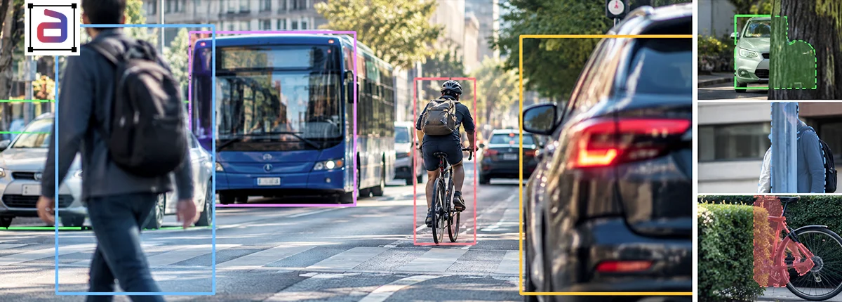
A 3D cuboid can have the correct center, width, length, and height and still represent an object incorrectly if its orientation is wrong.
The difficulty is that 3D cuboid orientation annotation is not defined by one universal yaw convention. Camera datasets, LiDAR datasets, robotics systems, and autonomous-driving frameworks can use different coordinate axes, reference directions, rotation signs, dimension orders, and orientation representations.
That means an annotation value such as yaw = 0 has little meaning unless the dataset also defines the coordinate frame and the direction that represents zero rotation.
For perception teams, the goal is therefore not simply to “label the angle.” It is to create orientation ground truth that is mathematically consistent, geometrically meaningful, and compatible with the training and evaluation pipeline.
This guide explains how to define those conventions and build QA controls around them.
Key Takeaways
- Yaw has meaning only when the coordinate frame, zero-angle direction, and positive rotation direction are explicitly defined.
- Camera, LiDAR, ego-vehicle, and world coordinate systems may represent the same object orientation differently.
- Some datasets encode only yaw, while others may store full 3D rotation using quaternions or additional rotational parameters.
- Symmetrical objects require explicit front-versus-rear rules because a 180-degree change may alter heading without changing the cuboid footprint.
- Orientation QA must handle angular wraparound correctly; +179° and -179° are only 2° apart.
- Cuboid orientation, position, dimensions, and object class should be validated together rather than as independent fields.
Table of Contents
- 1. What Does Orientation Mean in a 3D Cuboid?
- 2. Yaw Is Meaningless Without a Coordinate Convention
- 3. Camera, LiDAR, Ego and World Frames Are Not Interchangeable
- 4. Define Which Side of the Object Is “Front”
- 5. Handle 180-Degree Ambiguity Explicitly
- 6. Treat Angular Wraparound Correctly
- 7. Do Not Assume Every Dataset Uses Yaw, Pitch and Roll the Same Way
- 8. Separate Orientation From Motion Direction
- 9. Create Rules for Partially Occluded Objects
- 10. Use Sensor Evidence According to the Project Setup
- 11. Validate Box Dimensions and Orientation Together
- 12. Measure Orientation Error With the Right Metric
- 13. Add Automated Orientation Sanity Checks
- 14. Build a Dedicated Orientation Calibration Set
- 15. A 3D Cuboid Orientation Specification Checklist
- 16. How This Article Fits Annotera’s 3D Cuboid Content
- 17. How Annotera Supports Orientation-Aware 3D Cuboid Annotation
- 18. Conclusion: Orientation Quality Begins With a Convention
What Does Orientation Mean in a 3D Cuboid?
A 3D cuboid describes an object’s location and physical extent in three-dimensional space. Depending on the dataset or tool, a box may include a center position, three dimensions, and one or more rotation values.
A common 3D detection representation contains:
- x, y, and z position;
- length, width, and height; and
- an orientation value such as yaw.
Other formats may describe orientation using a rotation matrix, Euler angles, or a quaternion.
Annotera’s 3D cuboid annotation services support depth-aware labeling for camera, LiDAR, stereo, and other spatial-perception workflows. The required output convention should be defined according to the client’s sensor and training pipeline.
Yaw Is Meaningless Without a Coordinate Convention
Yaw generally describes rotation around the gravity or vertical axis. But that definition alone is not enough to interpret a number.
A usable annotation specification must also define:
- which axis is vertical;
- which horizontal direction corresponds to yaw = 0;
- whether positive rotation is clockwise or counter-clockwise;
- whether angles are stored in degrees or radians;
- the valid angle range;
- the object’s directional axis; and
- which coordinate frame the rotation belongs to.
These details are not universal across 3D perception systems.
For example, MMDetection3D documents separate camera, LiDAR, and depth coordinate systems and notes that yaw interpretation depends on the coordinate convention. Converting a 3D box from one frame to another can therefore require converting the yaw angle as well as the box center and dimensions.
Teams working across frameworks can review the MMDetection3D coordinate-system guide for a practical example of these differences.
Camera, LiDAR, Ego and World Frames Are Not Interchangeable
The same physical vehicle can have different numerical position and orientation values depending on the frame in which it is represented.
| Reference Frame | What It Represents | Annotation Consideration |
|---|---|---|
| Camera Frame | Coordinates relative to a particular camera | Axes usually follow camera geometry and may differ from LiDAR conventions. |
| LiDAR Frame | Coordinates relative to the LiDAR sensor | Often used for point-cloud 3D detection and bird’s-eye-view geometry. |
| Ego-Vehicle Frame | Coordinates relative to the vehicle or robotic platform | Useful when combining observations from several sensors. |
| Global / World Frame | Coordinates relative to a fixed environment or map | Useful for scene-level trajectories and multi-frame spatial reasoning. |
A project should not mix these representations without an explicit transformation process.
The nuScenes dataset, for example, stores sensor extrinsics relative to the ego-vehicle frame and represents sample-annotation orientation using quaternions. That is a different representation from simply storing one camera-relative yaw value.
Define Which Side of the Object Is “Front”
Orientation labels are most useful when an object’s directional axis is well defined.
For cars, buses, bicycles, and many mobile robots, front and rear are visually and functionally different. For other objects, orientation can be ambiguous.
Examples include:
- traffic barriers;
- cylindrical containers;
- square pallets;
- boxes with visually identical sides;
- some pieces of machinery; and
- partially visible objects whose front cannot be determined.
The annotation specification should state whether these classes:
- require a directional heading;
- have rotational symmetry;
- can receive an unknown-orientation attribute; or
- should use a canonical orientation defined by the project.
This is important because a 180-degree rotation can leave the geometric cuboid unchanged while reversing the heading of a directional object.
Handle 180-Degree Ambiguity Explicitly
A cuboid around a rectangular vehicle can occupy the same spatial footprint when rotated by 180 degrees. Geometry alone therefore may not reveal whether the annotated heading points toward the front or rear.
This creates two different QA questions:
| Question | Meaning |
|---|---|
| Is the box geometry correct? | Does the cuboid occupy the correct physical region? |
| Is the heading correct? | Does the orientation indicate the correct front-facing direction? |
A box can pass the first test and fail the second.
MMDetection3D notes that adding π radians to a cuboid yaw may leave its IoU unchanged even though it reverses the object’s heading. For direction-sensitive classes such as vehicles, this difference matters to orientation evaluation.
Treat Angular Wraparound Correctly
Angular values are periodic. That creates a common QA trap.
Suppose a reference vehicle orientation is:
+179°
and an annotation is:
-179°
A simple subtraction produces a difference of 358 degrees. Geometrically, however, the two headings are only 2 degrees apart.
Orientation QA should therefore calculate the shortest angular difference after normalizing the values to the project’s chosen angular range.
Do Not Assume Every Dataset Uses Yaw, Pitch and Roll the Same Way
Yaw, pitch, and roll are useful concepts for describing three-axis rotation, but a 3D object-detection dataset does not necessarily annotate all three.
Many ground-based detection benchmarks simplify object boxes to one rotational degree of freedom around the gravity axis. Other applications may require richer pose representations.
| Application | Possible Orientation Requirement |
|---|---|
| Road vehicles on a mostly planar road | Yaw may be the primary box-orientation parameter. |
| Drone perception | Platform and object pose may require additional rotational information. |
| Robotic manipulation | Full object pose may matter for grasping and interaction. |
| Warehouse mobile robots | Heading may dominate for navigation while object-specific pose requirements vary. |
| Industrial parts | Full rotation may be necessary when parts can appear in arbitrary orientations. |
The annotation format should follow the downstream task rather than assume that every spatial-AI dataset requires the same rotational degrees of freedom.
Separate Orientation From Motion Direction
An object’s heading and its velocity direction are related but not identical concepts.
A vehicle can reverse. A forklift can move backward. A pedestrian’s body orientation may differ from the direction of travel. A robot can rotate in place.
Therefore, a dataset should not automatically derive orientation from observed motion unless the project explicitly defines that method.
If the downstream system needs both signals, they should be represented independently:
- orientation: which direction the object itself faces;
- velocity: how its position changes over time; and
- trajectory: the path followed across a sequence.
This distinction becomes particularly important in temporal data. Annotera’s separate guide to orientation challenges in 3D video labeling focuses on maintaining orientation consistency as objects move and viewpoints change across frames.
Create Rules for Partially Occluded Objects
Orientation becomes harder to infer when only part of an object is visible.
A vehicle may be hidden behind another vehicle. A pallet may be partly blocked by shelving. A robot may disappear behind industrial equipment.
The annotation guide should define when orientation can be inferred and when it should be marked uncertain.
- Which visible features are sufficient to identify front versus rear?
- Can LiDAR geometry be used when camera evidence is ambiguous?
- Can neighboring frames be consulted?
- Should the previous cuboid orientation be propagated?
- At what visibility level must orientation be marked uncertain?
- Should the object remain annotated when heading cannot be established?
These rules should depend on the data modality and downstream task.
Use Sensor Evidence According to the Project Setup
Orientation evidence can differ substantially by sensor.
| Sensor / Data Source | Potential Orientation Evidence | Typical Limitation |
|---|---|---|
| Camera | Visual shape, headlights, windows, wheels, object appearance | Perspective and occlusion can create depth ambiguity. |
| LiDAR | 3D shape and point distribution | Sparse or distant objects may contain few points. |
| Radar | Range and motion information | Less detailed object shape. |
| Multi-Sensor Fusion | Combined visual, spatial, and motion evidence | Requires accurate sensor calibration and synchronization. |
For multimodal datasets, see Annotera’s guide to 3D cuboid annotation for LiDAR and sensor fusion, which focuses on cross-sensor correspondence rather than orientation conventions alone.
Validate Box Dimensions and Orientation Together
Orientation errors can sometimes be confused with dimension errors.
Consider a vehicle with length and width stored incorrectly. Rotating the cuboid by 90 degrees may appear to fix the geometry visually even though the underlying dimension convention is still wrong.
This is why the annotation specification should define:
- dimension order;
- which cuboid axis represents length;
- which side is considered front;
- the zero-yaw reference direction; and
- the coordinate system in which all values are stored.
Orientation QA should therefore be performed together with geometry validation rather than independently.
Measure Orientation Error With the Right Metric
The appropriate metric depends on what the annotation represents.
| QA Measure | What It Helps Detect |
|---|---|
| Angular error | Difference between annotated and reference heading |
| 180° flip rate | Front/rear reversal on directional object classes |
| 3D box overlap | Combined geometry and orientation alignment |
| Bird’s-eye-view overlap | Horizontal footprint consistency |
| Class-level orientation error | Object categories that create greater heading ambiguity |
| Reviewer agreement | Whether humans interpret orientation rules consistently |
| Uncertain-orientation rate | How often available sensor evidence is insufficient |
A good QA dashboard should also break orientation errors down by distance, visibility, class, sensor, scene type, and occlusion level where those dimensions are relevant.
Add Automated Orientation Sanity Checks
Some orientation errors can be identified automatically before human QA.
Useful validation rules may flag:
- angles outside the allowed range;
- unexpected units such as degrees in a radians-based pipeline;
- invalid quaternions;
- swapped length and width dimensions;
- orientation values inconsistent with the configured coordinate frame;
- sudden 180-degree flips in temporal data;
- unlikely class-specific box dimensions; and
- cuboids whose rotation produces impossible scene geometry.
Automated validation cannot determine every correct heading, but it can remove many structural errors before expensive visual review.
Build a Dedicated Orientation Calibration Set
Before scaling annotation, create a small calibration dataset that deliberately stresses the orientation rules.
Include examples such as:
- objects facing each major heading direction;
- objects near the angle wraparound boundary;
- front/rear ambiguity;
- symmetrical objects;
- heavy occlusion;
- distant sparse-LiDAR objects;
- objects seen from unusual camera viewpoints;
- stationary objects;
- reversing objects where video is used; and
- examples that should receive an uncertain orientation.
Multiple annotators should label the same examples. Disagreements then expose unclear reference-frame, front-axis, or ambiguity rules before those inconsistencies spread across a large dataset.
A 3D Cuboid Orientation Specification Checklist
Before production begins, the project owner should be able to answer all of these questions:
- Which coordinate system is used?
- Which axis represents gravity or vertical direction?
- Which direction corresponds to yaw = 0?
- Is positive yaw clockwise or counter-clockwise?
- Are angles stored in degrees or radians?
- What is the valid angular range?
- Which cuboid axis points toward the object front?
- What is the dimension order?
- Does the dataset store yaw only or full 3D rotation?
- How are symmetrical objects treated?
- How are front/rear ambiguities resolved?
- When can annotators use neighboring frames?
- How are partially occluded objects handled?
- When should orientation be marked unknown?
- How are coordinate transformations validated?
- How will angular wraparound be handled in QA?
- Which orientation-error metrics will be reported?
- How will convention changes be version controlled?
If these rules are missing, two technically skilled annotators can produce different yaw values for the same physical object while each believes the annotation is correct.
How This Article Fits Annotera’s 3D Cuboid Content
Orientation convention is one part of a broader 3D perception data strategy.
For a broader explanation of depth and the Z-axis in autonomous systems, see Cuboids for Autonomous Systems: Seeing the Z-Axis.
For autonomous-driving-specific cuboid workflows, read Training Self-Driving Cars with Depth-Aware 3D Cuboid Annotation.
And for orientation in sequences—where the problem becomes maintaining heading consistency as objects and sensors move—see Solving the Orientation Challenge in 3D Video Labeling.
How Annotera Supports Orientation-Aware 3D Cuboid Annotation
Annotera structures 3D cuboid annotation workflows around the coordinate convention, sensor configuration, object taxonomy, and output requirements of each perception project.
Projects can include custom cuboid schemas, orientation rules, reference-frame documentation, calibration datasets, occlusion protocols, class-specific heading rules, multi-stage QA, geometric validation, and sensor-aligned annotation workflows.
For projects involving multi-sensor spatial data, Annotera can also align 3D cuboids across camera and LiDAR inputs while maintaining consistent object classes, position, dimensions, and orientation conventions.
Conclusion: Orientation Quality Begins With a Convention
Yaw is not just an angle attached to a cuboid. It is an angle interpreted inside a specific coordinate system, relative to a specific reference direction and object axis.
Without those definitions, orientation labels can be internally inconsistent even when the numbers look reasonable.
Reliable 3D cuboid ground truth therefore begins by defining the coordinate frame, rotation direction, zero-angle reference, dimension order, front-axis convention, symmetry rules, occlusion handling, and QA metrics before annotation begins.
Once those conventions are explicit, orientation becomes measurable, transformable across coordinate systems, and useful to downstream perception models.
Building a 3D perception dataset for autonomy, robotics, or spatial AI? Talk to Annotera about your 3D cuboid annotation requirements and design the coordinate conventions, orientation guidelines, QA framework, and sensor workflow around your model.